Primary Flight Display
The Primary Flight Display, or PFD, is a key component in the cockpit. It is the main source of information about attitude, airspeed, altiude, orientation and can combine many more sensors into a coherent picture. The EYEVIONICS PFD offers multiple modes, such as 3D Terrain & Topographic Imagery (with EYEVIONICS Aviator) or a distraction-free airliner mode (with EYEVIONICS Pro PFD).
On This Page
PFD Configuration with the PFD Fold-Out
Any Panel with a PFD Portal will display a PFD Fold-Out at the top and bottom edges. This Fold-Out contains the configuration options for the EYEVIONICS PFD. It does not matter which PFD Fold-Out is used to change the PFD configuration.
Notable PFD Fold-Out Items
Altimeter Barometric Setting
To change the altimeter setting (referred to as Kollsmann window for analogue altimeters), open the PFD Fold-Out and tap BARO. A popup will open, offering you to change the altimeter setting.
This popup also allows toggling between inHg (inches of mercury) and hPa (hectopascal) units. Changing the altimeterunit here will change the altimeter unit in the entire EYEVIONICS user interface.
PFD Fold-Out Items
Baro
- Baro
-
Opens a popup to change the altimeter setting (referred to as Kollsmann window for analogue altimeters).
This popup also allows toggling between inHg (inches of mercury) and hPa (hectopascal) units. Changing the altimeterunit here will change the altimeter unit in the entire EYEVIONICS user interface.
CDI
- Nav
-
Select the NAV 1 source. This will affect flight director navigation source. The navigation source is visible in the HSI as a green arrow.
Supported sources are:- Off
- No NAV 1 source.
- NAV 1
-
The radio navigation receiver for the NAV 1 channel. Usually a VOR receiver.
Only available if equipped in aircraft. - TACAN
-
The TACAN radio receiver.
Only available if equipped in aircraft. - FMS
-
Flight Management System, either GPS, INS or similar.
Only available if equipped in aircraft.
- Bearing
-
Select the bearing indicator source. Displayed as an aquamarine blue arrow in the HSI.
Supported sources are:- Off
- No bearing source.
- ADF 1
-
ADF (NDB receiver).
Only available if equipped in aircraft.
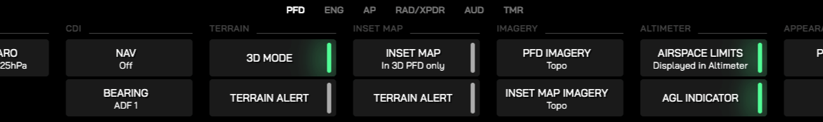
Terrain
- 3D Mode AVIATOR FEATURE
- Toggles the PFD between 3D Terrain mode and 2D mode.
- Terrain Alert AVIATOR FEATURE
- Toggles the Terrain Alert functionality for PFD 3D Terrain on or off.
Inset Map
- Inset Map AVIATOR FEATURE
- Toggles the Inset Map behind the HSI on or off.
- Terrain Alert AVIATOR FEATURE
- Toggles the Terrain Alert functionality for the Inset Map on or off.
Imagery
- PFD Imagery AVIATOR FEATURE
- Cycle through available imagery types for the PFD 3D Terrain.
- Inset Map Imagery AVIATOR FEATURE
- Cycle through available imagery types for the Inset Map.
Altimeter
- Airspace Limits AVIATOR FEATURE
-
Toggle airspace limits in altimeter on or off.
Learn more about this feature here. - AGL Indicator
-
Show or hide the AGL indicator below the altimeter.
The AGL indicator only appears when below 3,000ft AGL.
Appearance
- PFD Style Pro PFD FEATURE
-
Cycle through available PFD styles.
Supported styles are:- Default
- Default PFD style, supporting the 2D and 3D PFD modes.
- Airliner
-
Only available with EYEVIONICS Pro PFD.
While selected, 3D Terrain and Inset Map are be disabled.
Get it here.
- HSI Size
-
Cycle between available HSI sizes.
Useful for different flight phases (enroute vs approach) and for VFR and IFR. In IFR operations, the Minimal preset is often sufficient, allowing more space for other items on the PFD.
AHRS
- Horizon Headings
-
Toggle heading numbers along the PFD horizon line on or off.
When enabled, headings are displayed in 10 degree incremenets just under the horizon. - Partial Horizon Pro PFD FEATURE
-
Limit the PFD horizon to the center portion of the PFD.
Only available when PFD → PFD Style is set to Airliner.
Symbology
- Reference Symbol
-
Cycle between available aircraft reference symbols and associated flight director symbology in the PFD.
Available symbols are:- Inverted V
- A golden, inverted V shape.
- Wing
-
A shape resembling the profile of an aircraft.
Not available when PFD → PFD Style is set to Airliner. - Bars Pro PFD FEATURE
-
Symmetrical, L shaped bars.
Only available when PFD → PFD Style is set to Airliner.
- Show Traffic AVIATOR FEATURE
-
Show or hide traffic icons in the PFD.
In addition, for traffic icons to be displayed, all these conditions must be met:- PFD must be in 3D Mode. Enable with PFD → 3D Mode.
- Traffic must not be disabled in the MFD Fold-Out. Enable it with MFD → Traffic.
Flight Path Marker
- Flight Path Marker
- Toggle the Flight Path Marker icon on or off.
- Marker Inertia
-
Cycle between Flight Path Marker inertia modes.
Available modes are:- Normal
-
Flight Path Marker has default sensitivity.
Recommended for most aircraft. - Low
-
Flight Path Marker reacts more quickly to acceleration of the aircraft along any axis.
Consider this setting for highly nimble aircraft, such as aerobatics airplanes. - High
-
Flight Path Marker reacts more slowly to acceleration of the aircraft along any axis.
Consider this setting for medium and heavy weight category aircraft, such as airliners.
Other
- Pitch Limit Indicator
-
Toggle the Pitch Limit Indicator (PLI) on or off.
This indicator appears only when the bank angle is at or below 90° and when at least one of the following conditions is met:- Landing gear is not fully retracted
- AoA is higher than half the AoAcrit
- Indicated airspeed is less than 110% of the stall speed for the current aircraft configuration
- EYEVIONICS detects that the aircraft is performing a takeoff
- Suppress Stall
-
When enabled, stall warnings in the PFD are suppressed.
This setting is enabled automatically when EYEVIONICS detects a helicopter or VTOL aircraft.
The AoA indicator in the [SCSI](#secondary-control-surface-indicator-scsi) remains visible regardless of this setting and will turn red when the critical AoA is reached or exceeded.
PFD Modes
The EYEVIONICS PFD supports 3 modes:
- 2D Mode (Default style)
- 3D Mode (Default style, Aviator subscription required)
- Airliner (Pro PFD add-on required)
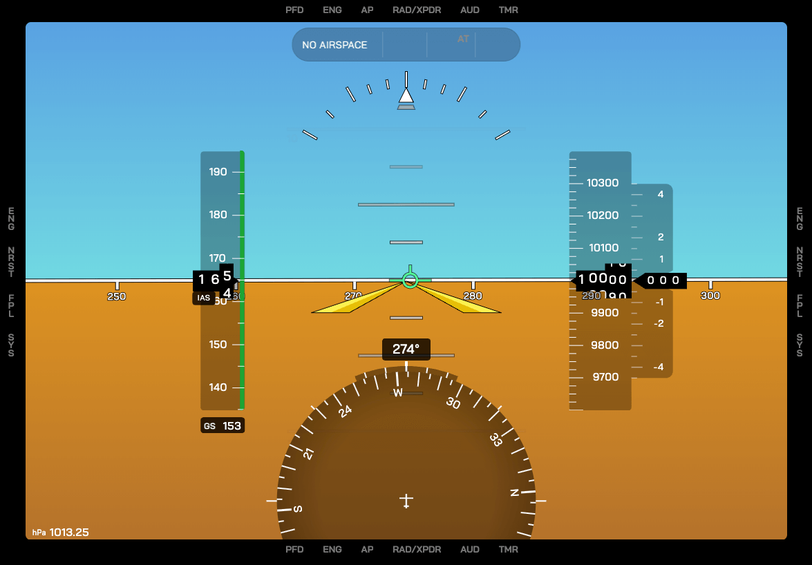
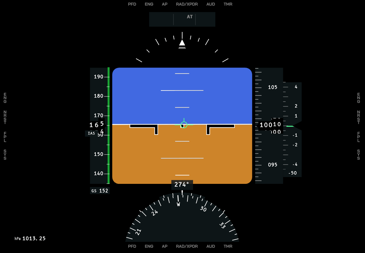
2D PFD Mode
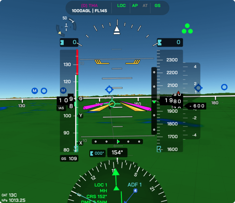
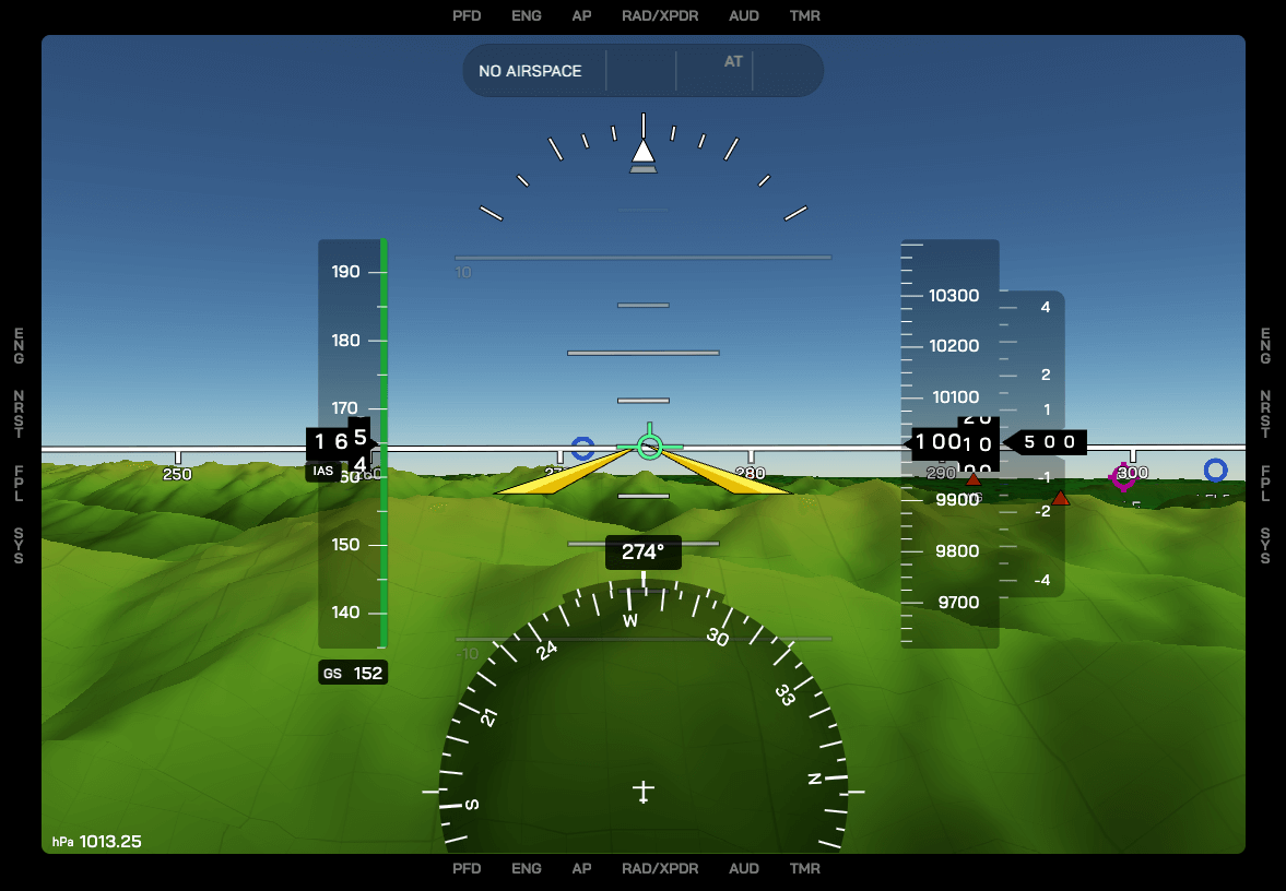
3D PFD Mode
Airliner PFD (Pro PFD)
Toggling Between PFD Modes
To toggle between the 2D and 3D mode, open the PFD Fold-Out and tap 3D Mode.
To enable the Airliner mode, open the PFD Fold-Out, scroll right and tap PFD Style.
3D Mode
When in 3D Mode, the PFD shows a terrain reference behind the PFD symbology. This terrain roughly matches what the pilot can see out the windshield of the aircraft in clear weather.
3D Terrain is not a replacement for visual contact with the ground. Avoid relying oly on 3D Terrain when flying in Instrument Meteorological Conditions (IMC) or low visibility.
3D Mode Imagery
To cycle between Imagery types for the PFD 3D Terrain, tap on PFD → PFD Imagery.
3D Terrain Accuracy & Precision
3D Terrain reliability depends on two factors:
- The accuracy of the 3D Terrain data
- The Terrain Quality setting of the EYEVIONICS App (see this page)
- The precision of altitude and position measurements
A horizontal resolution of ca. 30m can be assumed for 3D Terrain data. The precision of 3D Terrain symbology can be influenced by data of the following sensors, or the absence thereof:
- altimeter setting
- location data precision (GPS or similar)
- temperature measurement
As for the altitude measurement, it is up to the pilot to take the current altimeter setting into account when interpreting 3D Terrain symbology.
The closer the altimeter setting is to the actual environmental conditions, the more precise the 3D Terrain indication.
Non-Standard PFD Symbology
Secondary Control Surface Indicator (SCSI)
Since simulated flight cannot convey the feeling of the aircraft's acceleration along all of its axes, EYEVIONICS has developed the Secondary Control Surface Indicator to aid both in trimming the aircraft and to verify the state of secondary flight controls.
SCSI Location in PFD
 The SCSI is located over the speed tape in the EYEVIONICS PFD.
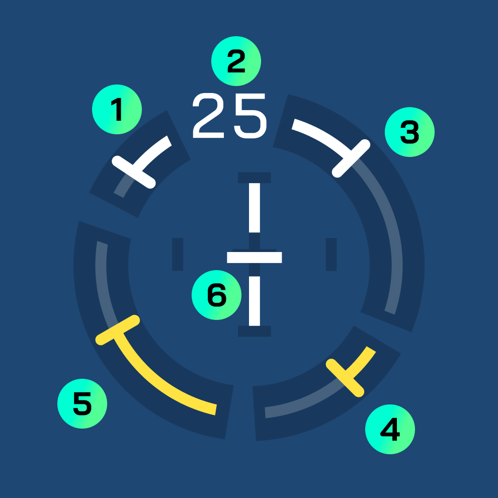
SCSI Indications
SCSI Indications
- Leading Edge Flaps ("Slats")
- Flap Handle Position in Percent (25% in this image)
- Trailing Edge Flaps
- Spoilers/Speed Brakes
- Angle of Attack
- Trim Indications (see image below)

SCSI Trim Indications
- Elevator Trim
- Aileron Trim
- Rudder Trim
SCSI Behaviour
Note that many aircraft with Fly-by-Wire systems change position of secondary control surfaces autonomously. This is reflected in the SCSI, usually by changing position of flap and slat bars.
The SCSI Trim Indicator will disappear a few seconds after trim was changed. When autopilot is engaged, the SCSI trim indicator will appear whenever the autopilot changes aircraft trim.
Airspace Situation Indicator
EYEVIONICS displays information about the current airspace at the top of the PFD. When inside multiple airspace boundaries, EYEVIONICS prioritises airspaces by the amount of restrictions they impose. Only the most restrictive airspace will be displayed here.
By tapping the airspace information, the airspace boundaries will be highlighted in 3D.
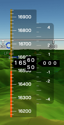
Altimeter Airspace Indications
The altimeter in the EYEVIONICS PFD can display airspace boundaries. Similar to the Airspace Situation Indicator, in case the aircraft is within multiple airspaces, the most restrictive airspace type is displayed. These indications can be disabled or enabled by tapping PFD → Airspace Limits.
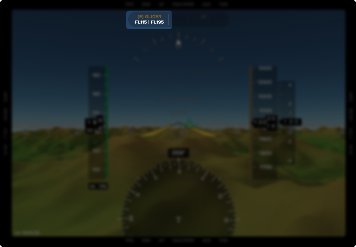
Example: Altimeter Airspace Indications
In this case, the aircraft is descending through 16,500ft MSL, where it can expect to cross from a glider area (brown yellow) into a restricted (orange) airspace.Even though the glider area in this example extends from FL115 up to FL195 and the restricted airspace extends only up to FL165, the restricted airspace has a higher priority and therefore, it is displayed over the glider area.